Specifications
Shaft Size |
N/A 400 mm |
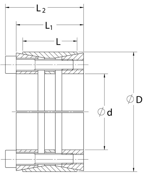
d |
N/A 15.748 in |
D |
N/A 19.488 in |
L |
N/A 5.512 in |
L1 |
N/A 6.299 in |
L2 |
N/A 7.165 in |
Mt |
N/A 449,941 ft-lbs |
Fax |
N/A 685,710 lbs.F |
Ps |
N/A 24448 psi |
Ph |
N/A 19756 psi |
| DN1 | N/A 31.212 in |
Locking Screws Quantity |
N/A 22 |
Locking Screws Size |
N/A M22 x 130 |
Ma-Locking Screws |
N/A 686 ft-lbs |
Hub Machining Tolerance |
N/A 0.004 in |
Shaft Machining Tolerance |
N/A -0.004 in |
Weight |
N/A 167.00 lb |
UPC Code |
N/A 044861047583 |
Downloads |
N/A
Catalog Page Installation & Removal Instructions Installation Demonstration (Video) Keyless Locking Technical Information |
- 1 Minimum hub outside diameter based on a Pressure reduction Factor of C=1.0 and hub material with tensile yield point = 45,000 psi. For details see Hub Strength in Technical Information.