Specifications
Shaft Size |
N/A 100 mm |
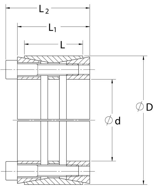
d |
N/A 3.937 in |
D |
N/A 5.709 in |
L |
N/A 2.362 in |
L1 |
N/A 2.835 in |
L2 |
N/A 3.307 in |
Mt |
N/A 14,333 ft-lbs |
Fax |
N/A 87,374 lbs.F |
Ps |
N/A 31152 psi |
Ph |
N/A 21484 psi |
| DN1 | N/A 9.599 in |
Locking Screws Quantity |
N/A 10 |
Locking Screws Size |
N/A M12 x 60 |
Ma-Locking Screws |
N/A 107 ft-lbs |
Hub Machining Tolerance |
N/A 0.003 in |
Shaft Machining Tolerance |
N/A -0.002 in |
Weight |
N/A 8.80 lb |
UPC Code |
N/A 044861047309 |
Downloads |
N/A
Catalog Page Installation & Removal Instructions Installation Demonstration (Video) Keyless Locking Technical Information |
- 1 Minimum hub outside diameter based on a Pressure reduction Factor of C=1.0 and hub material with tensile yield point = 45,000 psi. For details see Hub Strength in Technical Information.