Specifications
Shaft Size |
N/A 9 mm |
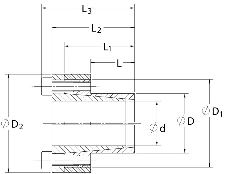
d |
N/A 0.354 in |
D |
N/A 0.630 in |
D1 |
N/A 1.024 in |
D2 |
N/A 1.142 in |
L |
N/A 0.551 in |
L1 |
N/A 0.945 in |
L2 |
N/A 1.063 in |
L3 |
N/A 1.220 in |
Mt |
N/A 32 ft-lbs |
Fax |
N/A 2,191 lbs.F |
Ps |
N/A 29753 psi |
Ph |
N/A 16736 psi |
| DN1 | N/A 0.931 in |
Locking Screws Quantity |
N/A 4 |
Locking Screws Size |
N/A M4 x 10 |
Ma-Locking Screws |
N/A 3.7 ft-lbs |
Hub Machining Tolerance |
N/A 0.002 in |
Shaft Machining Tolerance |
N/A -0.002 in |
Weight |
N/A 0.40 lb |
UPC Code |
N/A 044861077863 |
Downloads |
N/A
Catalog Page Installation & Removal Instructions Installation Demonstration (Video) Keyless Locking Technical Information |
- 1 Minimum hub outside diameter based on a Pressure reduction Factor of C=1.0 and hub material with tensile yield point = 45,000 psi. For details see Hub Strength in Technical Information.