Specifications
Shaft Size |
N/A 35 mm |
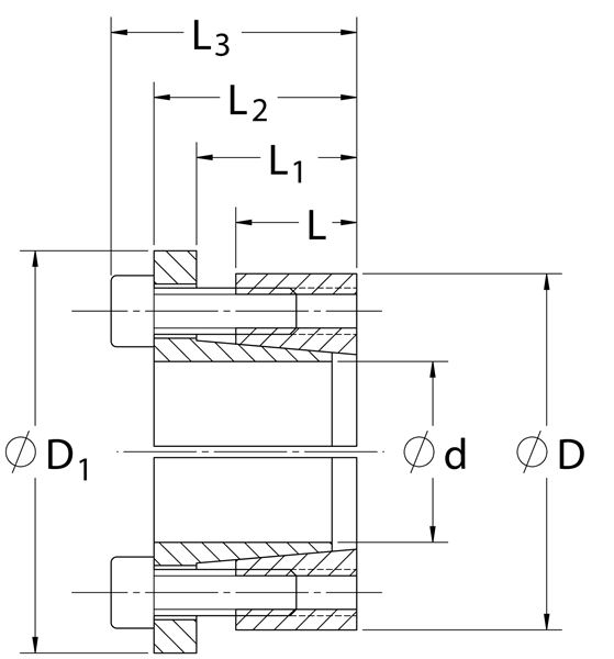
d |
N/A 1.378 in |
D |
N/A 2.125 in |
D1 |
N/A 2.250 in |
L |
N/A 0.669 in |
L1 |
N/A 0.829 in |
L2 |
N/A 1.102 in |
L3 |
N/A 1.299 in |
Mt |
N/A 6,060 in-lbs |
Fax |
N/A 8,796 lbs.F |
Ps |
N/A 25,309 psi |
Ph |
N/A 16412 psi |
| DN1 | N/A 3.115 in |
Locking Screws Quantity |
N/A 10 |
Locking Screws Size |
N/A M5 x 18 |
Ma-Locking Screws |
N/A 89 in-lbs |
Hub Machining Tolerance |
N/A 0.001 in |
Shaft Machining Tolerance |
N/A -0.001 in |
Weight |
N/A 0.60 lb |
UPC Code |
N/A 044861046852 |
Downloads |
N/A
Catalog Page Installation & Removal Instructions Installation Demonstration (Video) Keyless Locking Technical Information |
- 1 Minimum hub outside diameter based on a Pressure reduction Factor of C=1.0 and hub material with tensile yield point = 45,000 psi. For details see Hub Strength in Technical Information.