Specifications
Shaft Size |
N/A 80 mm |
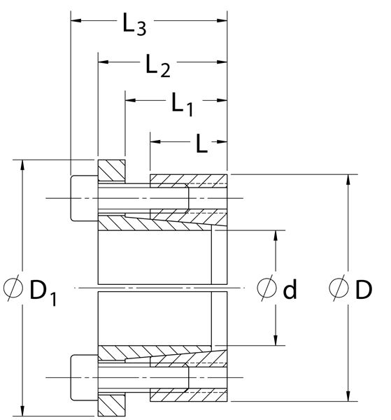
d |
N/A 3.150 in |
D |
N/A 4.724 in |
D1 |
N/A 5.079 in |
L |
N/A 0.945 in |
L1 |
N/A 1.201 in |
L2 |
N/A 1.594 in |
L3 |
N/A 1.988 in |
Mt |
N/A 3,990 ft-lbs |
Fax |
N/A 30,403 lbs.F |
Ps |
N/A 27,099 psi |
Ph |
N/A 18066 psi |
| DN1 | N/A 7.229 in |
Locking Screws Quantity |
N/A 8 |
Locking Screws Size |
N/A M10 x 30 |
Ma-Locking Screws |
N/A 61 ft-lbs |
Hub Machining Tolerance |
N/A 0.002 in |
Shaft Machining Tolerance |
N/A -0.002 in |
Weight |
N/A 4.10 lb |
UPC Code |
N/A 044861075623 |
Downloads |
N/A
Catalog Page Installation & Removal Instructions Installation Demonstration (Video) Keyless Locking Technical Information |
- 1 Minimum hub outside diameter based on a Pressure reduction Factor of C=1.0 and hub material with tensile yield point = 45,000 psi for carbon steel and a tensile yield point = 30,000 psi for stainless steel. For details see Hub Strength in Technical Information.